OmegaCAD Base package
Scope of application
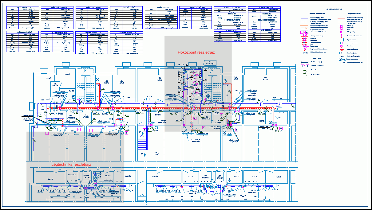
The OmegaCAD base-program 2D CAD system can be used under the wide-spread MS WINDOWS operation system. This fact determines the appearance of the program. Usage of its editing functions can easily be learned even without having qualification in the information technology. The menu system and the help system , - which are available during running the program, - can provide a great help for that. Main purpose of OmegaCAD base-program is to provide the design systems based upon that [for example electrotechnical design on heavy current, external electric network planning, etc. ...] such services, which make their appearance uniform and ensure the use of the general editing functions. By the use of the editing function of OmegaCAD Base package system any type of 2D engineering drawing can be produced.
Main functions of the program
Functions ensuring of the adjustment of user desktop
- By using the toolbox function specific toolboxes can be set up. These can be visualized, switched off according to the actual needs of the user. The work-area appearing on the screen can be changed in a flexible way, no matter it is a scroll-track, a message field, etc...
- The colours of main areas of the screen can be adjusted according to the needs, for example: background colour of the desktop, colour of the message area, highlighting colour, colour of the background layers, etc...
- The Drawing Lines function on the drawing can be used for mixing 32 different colours as well as for adjusting 8 different values of the line thickness.
- By using the Drawing Fontset function the required font can be adjusted.
Editing functions of OmegaCAD base-program
- The program solves handling of drawings, layers: saving, loading, renaming, printing, adjustment of the size and scale.
- Graphic elements, that can be placed on drawings: line chain, circle, arc, text, filling, symbol, scanned drawing [in BMP file format], database element. (Placing of database elements can only be done by using the database module or the extension module!)
- The properties of the graphic elements can be adjusted, for example: colour, size, line thickness, line type, direction and positioning of captions,... etc.
- A selected part of an edited drawing [block] can be deleted, moved, copied, reflected, turned off or stored on floppy disk as a graphic block. The stored graphic block can be placed on drawings even in reduced or magnified size.
- In the course of prescribing points for editing and placing of elements, the user has a lot of support [gridpoint, existing point, intersection point, ....]. During editing more than one auxiliary coordinate system can be prescribed and used.
- The Dimensioning function extensively supports the prescription of sizes of edited elements. The points determining the distances can be prescribed by point-input or by automatic calculation of intersection points. By some clicks the dimensioning of the radius or the diameter of a circle or an arc can easily be produced. Prescription of angles is supported by several functions.
- The user is supported by a lot of modificating functions, for example: changing of the style of layer lines, changing the layer of an element, changing of the properties of elements, etc...
- By the querrying functions the properties of elements placed on the drawings, coordinates of points can be obtained, as well as distances and directional angles can be measured.
- The exchange of drawings with other design systems is realised by the export and import functions of DXF.
 |
System requirements
The necessary operation system: WINDOWS 7, 8.1, 8.2, 10.
