OmegaCAD ELEKTRO
Scope of application
OmegaCAD ELEKTRO is an electrotechnical design system. It is for producing the complete documentation of electric equipment of high complexity, or for transferring of an existing documentation into computer systems. The system , - depending on its build up - is capable to solve different kind of tasks, from current path design up to producing of substation plans. The system is available in four different build-up, their description can be found on different pages:
- "Mini" current path design system
- "Midi" distributing design system
- "Complex" design system
- "PRO-INFO" project information system
The program package is based on MSZ 12897 standard, but its sysmbol system meets the requirements of IEC 750 and DIN 40719 standards too. Its easily handable menu system, messages and error messages, error- recognising routines provide efficient help in all phases of planning. The system extensively supports the creating part of the design process, while it performs by itself the algorithmisable tasks [numbering of terminal blocks, allocation of cables and cable cores, producing of mounting planes from current-path layouts, producing tables, etc.]. Its intelligent component-part searching procedures [ searching for sub-units, cable cores, terminal blocks] give support for the operation and trouble shooting.
Main modules and functions of the programme
OmegaCAD ELEKTRO follows the phases of the planning process, which is reflected in the module-type build-up of the system. This build-up makes possible for the users to apply parts of the programme independently from the others, to form from the modules realting to each other a design system meeting the demands. The essential part of the system is the main database, which is in connection with all the modules. The database contains the drawing marks, symbols applied in the current-path plan. A part of the devices can be built up by using such symbols. Devices with higher complexity (protective and automatic systems] can be defined as "black boxes" , by the functions of their connection points. Single line and outline drawings can be assigned to the devices, by which simplified circuit diagrammes [single line drawing] or layout plans can be produced. In further parts of the database, information on terminal blocks, cables and other materials can be sorted. The user can form the main database freely, according to his demands. Current path plans can be simply assembled with the help of symbols, device build-ups and other elements stored in the database. Editing is extensively supported by block operations, which make possible to transfer ready plans, parts of plans into other plans, plan pages. The graphic device and cable tables appearing at the end of the plan help navigation on the current path.
Sample drawing |
|
| Current path plan page | 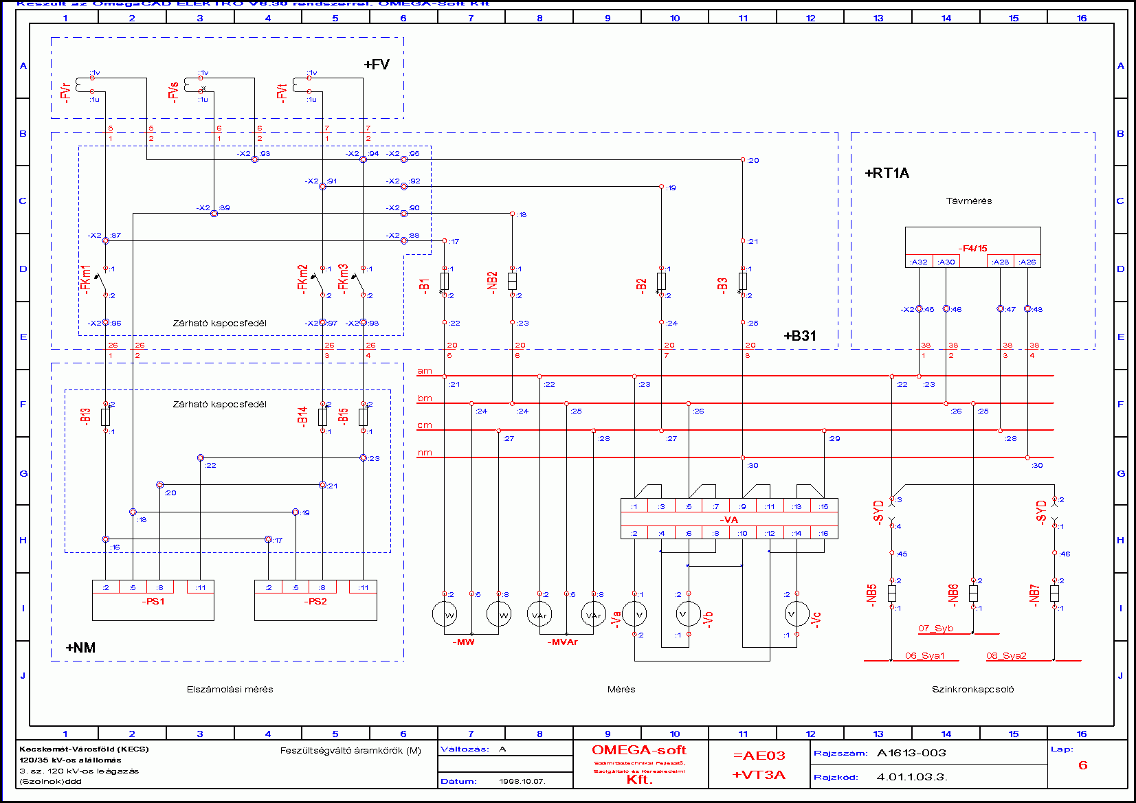 |
The finished plan is evaluated by the module analysing the current path plan. This performs the automatic numbering of cable cores and terminal blocks, taking into account the allocation and priorities prescribed by the designer in advance too. The result of the analysis is written back to the current path plan pages. Mounting planes can be generated from the evaluated plans automatically. The demonstrative terminal block-, device-, and cable connection plans extensively help the accurate realisation. The subsequent modification, - not applying to the current path, - gives suitable support for documenting the state of arts.
Sample drawing |
|
| Terminal block connection plan | 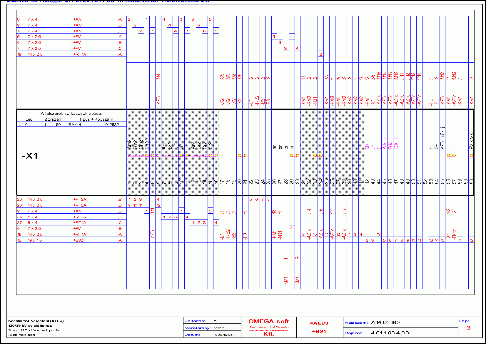 |
| Cable connection plan | 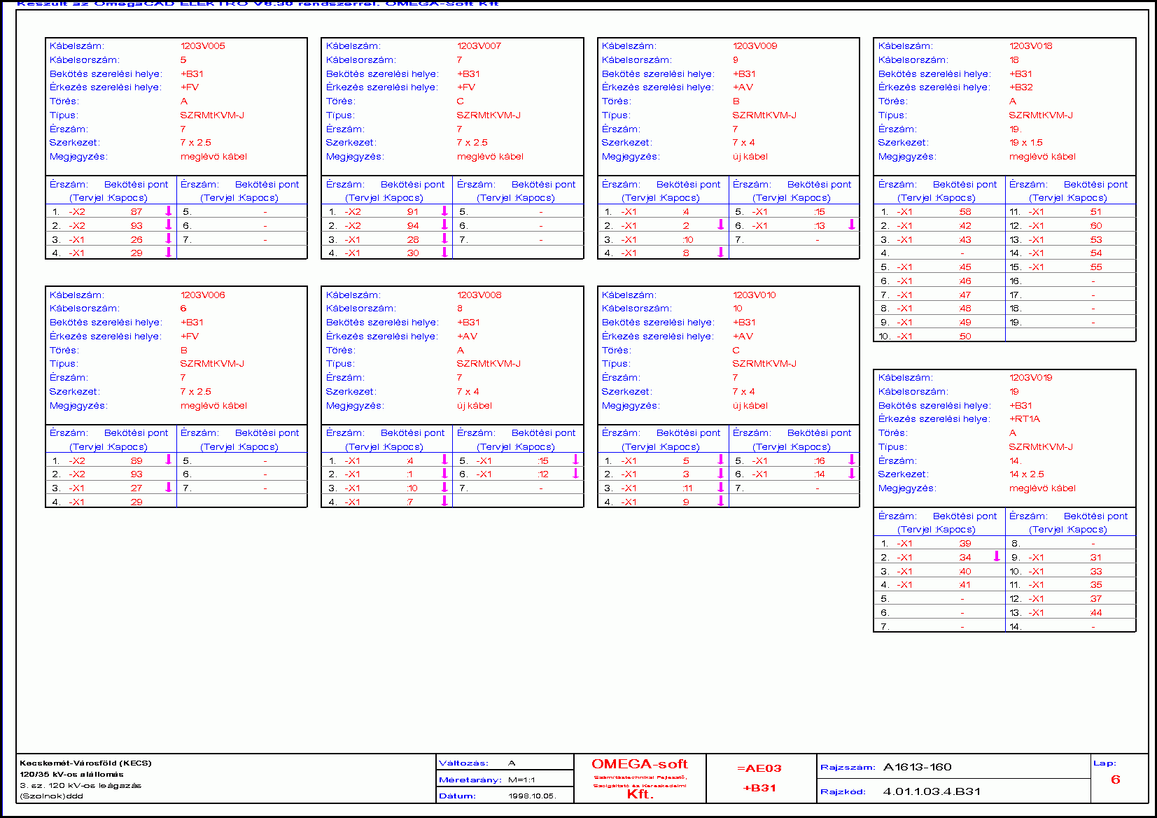 |
The system sorts out the devices on different mounting places. With the help of outline drawings assigned to the devices in the main database, dimensioned plans with any scale can be produced then. Its general purpose module, - summarising of the editing procedures of different kind of plans, - makes possible to produce any kind of engineering design in a simple way. Handling the other type of plans such as primery design sheets, or detailed iron-construction shop drawings in the same way, means a further increasement regarding the complexity of the system. Determining the necessary qauntity of cables as well as the number of cabcores, the system supports producing cable plans too. It submits these data according to types prescribed in the cable database.
Sample drawing |
|
| Device connection plan | 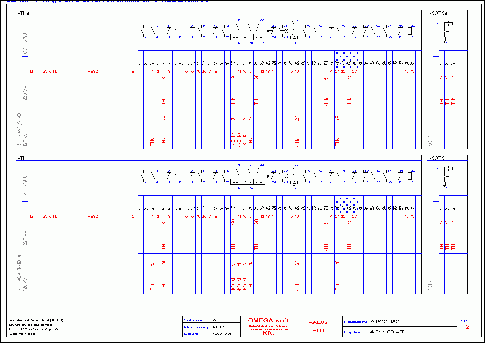 |
In the main database price or mounting time norm data applying to a given material can be prescribed both for devices, cables, terminal blocks and for other materials not appearing on the current path plan. With the help of these, the specification and the estimate of a given task can be simply produced. By the DXF export - import module the system can be related to different graphic systems. The lists and sorting out produced by the system, - such as distributing mounting, subtitling, - can be transferred to other systems by the dBASE format. OmegaCAD ELEKTRO is an extremely well-structured system, therefore despite its great size it can be easily viewed and the work with it can be easily learned, which is supported by an on-line help with detail description of the each commands. Nevertheless the developers are happy to train users in the frame of an organised training. For plans with different complexity systems with different performance are at disposal: The complete version of OmegaCAD ELEKTRO system is for producing complete primary and secondary design sheet plans for substations of electric energy transfer. OmegaCAD ELEKTRO Mini is a current path design system, which supports current path planning or current path analysis. OmegaCAD ELEKTRO Midi contains mounting and layout planning besides current path planning.
Sample drawing |
|
| Device table | 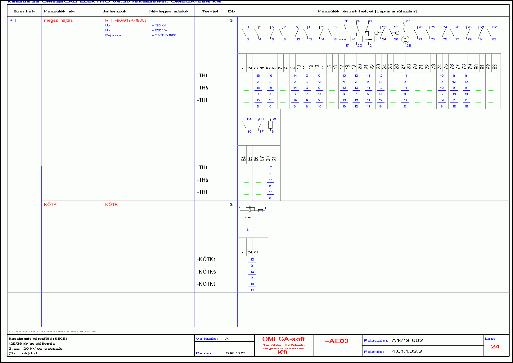 |
| Cable table | 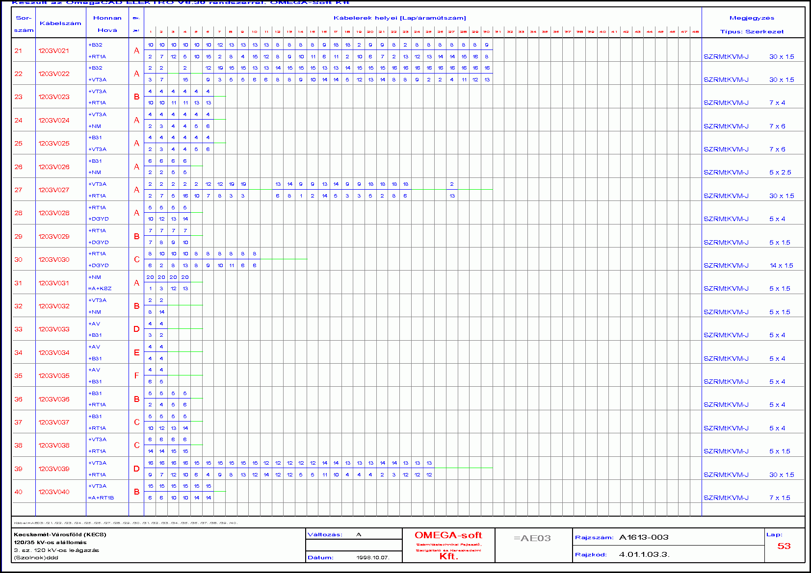 |
The design system is continually developed. Developing ideas are set up by taking into account the user's experiences. The advantages provided by the new functions increase the popularity of OmegaCAD ELEKTRO.
Sample drawing |
|
| Single line plan | 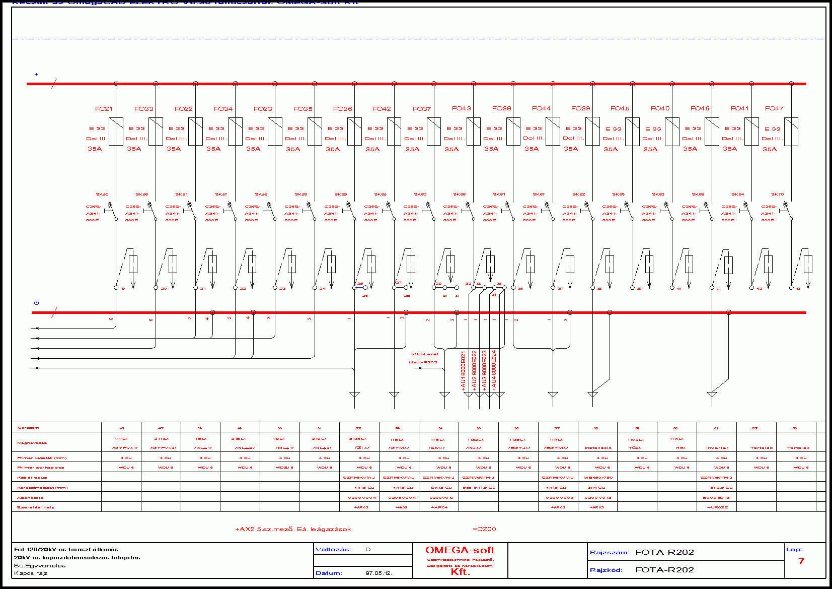 |
System requirements
OmegaCAD ELEKTRO runs on personal computers, under Windows 7, 8.1, 8.2, 10 operation system. It is possible to use the design system in a network too. For great construcion works it is advisable to choose systems with bigger performance, with a screen (monitor) and a printer necessary for graphic workstations.
Computer configuration recommended:
- The necessary operation systems: Windows 7, 8.1, 8.2, 10.
- Computer: suitable to use the operation system.
Sample drawings:
| The plan sheets of the First plan and the inspection of the identification system printed in PDF |
|
| Plan sheets of the sample plan printed in PDF |
|
| Plan sheets of the distributrion plan printed in PDF |
|